32 System Diagram 33 Connection Procedure Step1 Connect an HDMI source (such as a set top box) to the HDMI IN port of the transmitter with an HDMI cable Step2 Connect HDBT OUT port of the transmitter to HDBT IN port of the receiver using a twisted pair cable Step3 Connect an HDMI display to HDMI OUT port of the receiver with an HDMIThe official KYMCO TOP BOY 50, TOP BOY 100, Cobra 50 Scooter Service and Repair manual is now available online from CYCLEPEDIA PRESS LLC This online service manual features detailed, photographs and wiring diagrams, complete specifications with stepbystep procedures KYMCO TOP BOY 50, TOP BOY 100, Cobra 50 four stroke Scooter owners who need toToyota T100 Wiring Diagram Printer Friendly Version Listed below is the vehicle specific wiring diagram for your car alarm, remote starter or keyless entry installation into your Toyota T100 This information outlines the wires location, color and polarity to help you identify the proper connection spots in the vehicle

Abf Engine Wiring Diagram
Tp 100 module wiring diagram
Tp 100 module wiring diagram-Jun 17, 19 · Assortment of rtd pt100 3 wire wiring diagram A wiring diagram is a streamlined standard photographic depiction of an electrical circuit It shows the components of the circuit as streamlined shapes, and also the power and also signal links between the gadgetsDescription Pt100 3 Wire Circuit Diagram 3 Wire Rtd Connection Wiring Diagrams throughout Pt100 Wiring Diagram, image size 473 X 291 px, and to view image details please click the image Here is a picture gallery about pt100 wiring diagram complete with the description of the image, please find the image you need We hope this article can help in finding the information you


02 Grand Am Engine Diagram Wiring Diagram Overview Device Halt Device Halt Aigaravenna It
KMS TP 100/001 (basic version with 3phase AC motor) Splined coupling for connection to the valve shaft Machined coupling with bore and keyway Valve attachment Dimensions according to EN ISO 5211 1) Based on 68° F ambient temperature and at an average load with running torqueRB100 Ignition Control Module WELLS RB100 Ignition Control Module Direct Details» CARQUEST Ignition Control Module CARQUEST Ignition Control ModuleRichard thompson 1 1 0728 am Help with engraving?
Collection of pt100 sensor wiring diagram A wiring diagram is a simplified conventional pictorial representation of an electrical circuit It reveals the components of the circuit as simplified forms, and the power as well as signal links in between the gadgetsThe wiring diagram service provides the wiring diagrams for our products according to Order/Commission no Wiring diagram number Quotation number in PDF format Selected wiring diagrams (under "Documents") Attention The wiring diagram opens in a popup window If the popup blocker is turned on in your browser, you are not able to view theJul 30, 18 · rtd pt100 3 wire wiring diagram – What is a Wiring Diagram?
TP /2 AFABAQERX1 Product number Suitable for Commercial air conditioning Commercial heating Commercial hot waterJul 23, 15 · This design features a singlechip solution to linearize and transmit a 3wire PT100 RTD over the industry standard 2wire 4mA current loop The design was configured for a 0°C to 800°C temperature range, but other temperature ranges can be achieved by adjusting the component values as discussed in the Theory of Operation section of theJob wiring diagram and in compliance with national and local electrical codes Class I wiring is required unless all circuits to contacts are powered from a Class II source (See Figures 7 through 9 for typical wiring diagrams) 4 Hook thermostat on top of mounting plate and swing down into place 5 Tighten thermostat mounting screw


02 Grand Am Engine Diagram Wiring Diagram Overview Device Halt Device Halt Aigaravenna It


Gm Ls3 Engine Diagram Plaster Paveme All Wiring Diagram Plaster Paveme Apafss Eu
Nov 24, · Assortment of intermatic timer t104 wiring diagram A wiring diagram is a streamlined traditional photographic depiction of an electrical circuit It reveals the components of the circuit as streamlined forms, and also the power and also signal links between the gadgets6 The controller will measure the wire resistance and subtract it to leave us with just the PT100 resistance 7 In our sketch below we have the following resistances, Rpt, R1, R2 and R3 8 Mathematically the controller does the following calculation 9 Rpt = "the measurement between A and B" less "the resistance measured between B and C" 10Support 2 1 1152 am GCode that will allow linear interpolation of Z during XY G02 arc Ed Miles


Tp100 Wiring Diagram 1997 F250 Hd Wiring Diagram Rcba Cable Diau Tiralarc Bretagne Fr
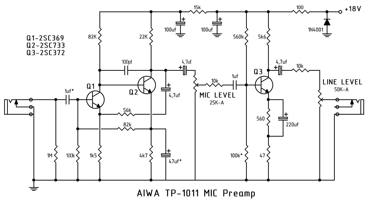


Diagram Ritchie Blackmore Wiring Diagrams Full Version Hd Quality Wiring Diagrams Diagramreklam Mariocrivaroonlus It
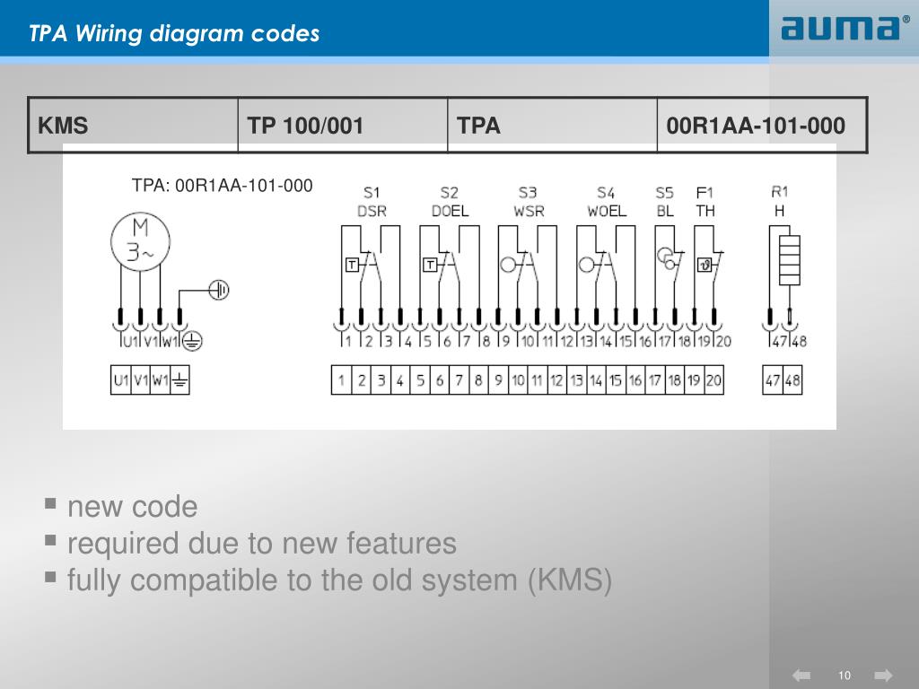
Apr 02, 18 · AUMA Wiring Diagrams New Wiring Diagram Designation S NORM AC1 AC2 Dimensional Diagrams Where to find wiring diagrams ging Information 2 New wiring diagram designations TPA Wiring diagram codes KMS TP 100/001Pt Wiring Diagram Asv Rtd Best 3 Wire Floralfrocks And Inside 3 Wire Range Wiring Diagram And Pt Saleexpert Me Inside Asv Wiring Diagram Wiring Diagram Schemes • asv wiring diagram wiring diagram will be a thing u rh exploreandmore co uk Dynatek Asv Rc Wiring schematronorg Free Download Here ASV RC Track Skid Steer Ats EquipmentRtd pt100 3 wire wiring diagram – A Beginner s Guide to Circuit Diagrams An initial look at a circuit layout might be complicated, yet if you could check out a subway map, you can check out schematics The function coincides receiving from point A to aim B Literally, a circuit is the path that permits electricity to circulation If you
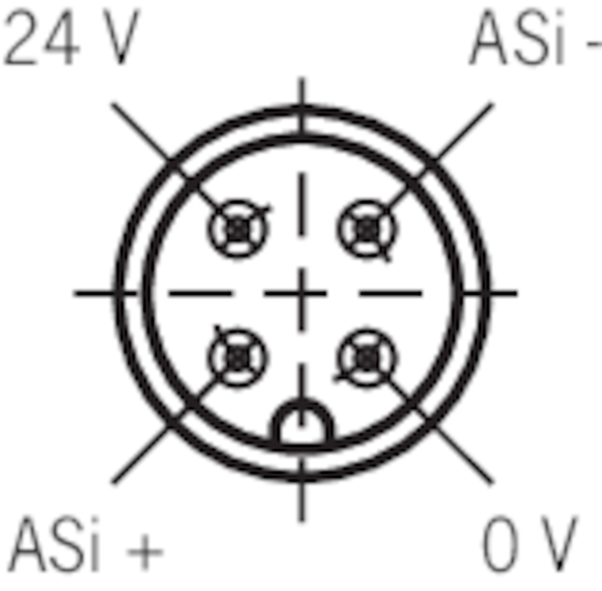


Stp3a 4141a024sem4as1 Safety Switch Stp Asi Plug Connector M12 Closed Circuit Current Principle Euchner More Than Safety


Ycsa Lca Ycsa H Braw 50 60 80 100 T Tp Pdf Free Download
Webasto thermo top c wiring diagram along with webasto thermo top c wiring diagram on as well as simple wiring diagram car s together with mercruiser tilt trim fuse moreover jaguar xj type wiring diagram furthermore thermo top c wiring diagram get free image about in addition wabco trailer abs wiring furthermore 1957 chevy wiper motor wiring diagram further dDicktator TP100 Ignition Module incl Plug & PinsNov 01, 13 · Where to Use TP, TPN and 4P in Distribution panel For any Distribution board, the protection system (MCB) must be used in the incomer For a three phase distribution panel either TP or TPN or 4P can be used as the incoming protection TP MCB It is most commonly used type in all ordinary three phase supply


1pc Touch Lighting Control Mt 1001 100v 1v 150w 60hz Dimmer Halogen Tungsten Led Light W Wire Nuts Switches Aliexpress


02 Grand Am Engine Diagram Wiring Diagram Overview Device Halt Device Halt Aigaravenna It
ModuSat (TP) Twin Plate Satellite Heating Unit Installation, Commissioning and Servicing Instructions B Evinox Energy Ltd T 44 (0)1372 E info@evinoxenergycouk W wwwevinoxenergycoukJul 22, 10 · In the pin out charts below is a brief job description of what each wire does NOTE Although I've included the color of the wires, in the charts below, I can tell you that they are not gonna' match the colors that are on your vehicle (it's been my experience that the colors described on the wiring diagrams usually never matches what's on the VW)Sellers rapid response boilers, deaerators, water heaters, and ancillary equipment Up to 90% less maintenance Best in the Industry A very long life of Sellers boilers and heaters A very long life of Sellers boilers and heaters Proudly made in the


2l 8v Gotech Help The Volkswagen Club Of South Africa
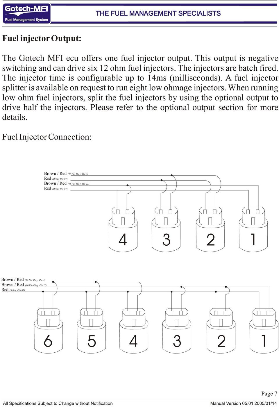


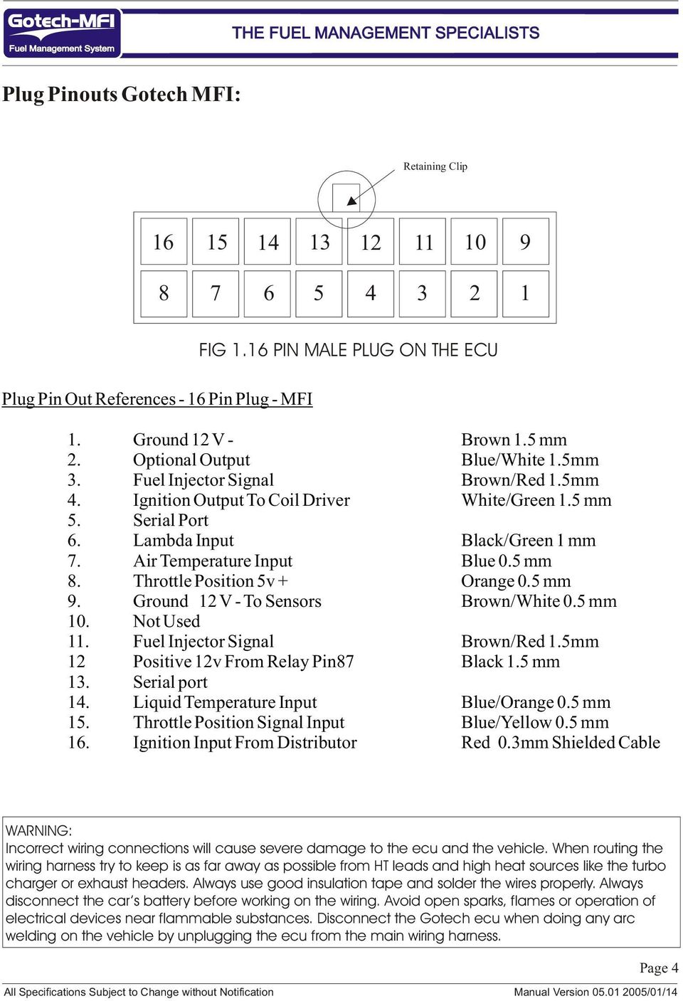
Mfi Instructional Manual Version Pdf Free Download
Using TP100 for zeroing X/Y on a fixture?PT100 Temperature Sensor Wiring Diagram 3 wire Pt100 RTD Sensor Wiring System The addition of a third wire, connected to one side of the measuring element, helpsNov 15, 16 · For example, here's the approximate resistances of a 4Wire PT100 RTD at 0 ° C (for a PT1000, the middle resistance would be (1002 Ω rather than 102 Ω) (Remember that the middle resistance 102 or 1002 Ω will vary with temperature, but the 2 Ω wires will not) When the amp measures this sensor, it will measure the resistance between one set of red and blue wires


6ly2a Stp Wiring Diagram Page 4 Line 17qq Com


Tp Link Smart Switch Red Wire Single Pole Page 1 Line 17qq Com
Wiring diagram KMS TP 100/001 Power supply 1phase 230VAC 50 Hz Wiring diagram KMS1 TP Clockwise rotation Anticlockwise rotation Legend S1 DSR Torque limit switch, closing, clockwise rotation S2 DÖL Torque limit switch, opening , anticlockwise rotation S3 WSRTravel limit switch, closing, clockwise rotationWiring diagrams AC 230 V, open/close Connection 3 takes priority AC 230 V, 3point 0 1 0100% S1 S2 S3 0 1 0 1 1 23 N L S1 S2 S3 1 0 1 0 1 1 23 N L 1 23 S1 S2 S3 0 1Jan 26, 10 · Pin 1 goes to negative coil so double check that and make sure you getting 12v on the positive coil wire I would suggest having the distributor and module removed and taken to a distributor specialist to test if you dont come right


Volvo 960 1993 Wiring Diagrams


Tp Link Smart Switch Wiring Diagram Page 1 Line 17qq Com
Jul 30, 18 · Use wiring diagrams to assistance with building or manufacturing the circuit or computer They are also ideal for making repairs DIY enthusiasts use wiring diagrams but you are also common in home based building and auto repairFor example, a home builder should read the physical location of electrical outlets and lightweight fixtures utilizing a wiring diagram in orderTP 110 /001 2) TP 100 /001 Basic equipment SA Basic equipment SAR/SG S 1 S 2 DSR DOEL Torque switch, closing, clockwise Torque switch, opening, counterclockwise S 1/2 S 2/2 DSR 1 DOEL 1 Torque switches, in tandem operation with DSR/DOEL S 3 S 4 WSR WOEL Limit switch, closing, clockwise Limit switch, opening, counterclockwise S 3/2 S 4/2 WSR 1 WOEL 11Wire Alternator Instructions / All Alternators PDF Download Adjustable Electric Fan Controller Instructions HC7110 / HC7111 PDF Download ES1001 Alternator Dimension PDF Download ES1004 Alternator Dimension PDF Download ES1005 Alternator Dimension PDF Download ES1006 Alternator Dimension PDF Download ES1013 1Wire setup Instructionspdf PDF Download
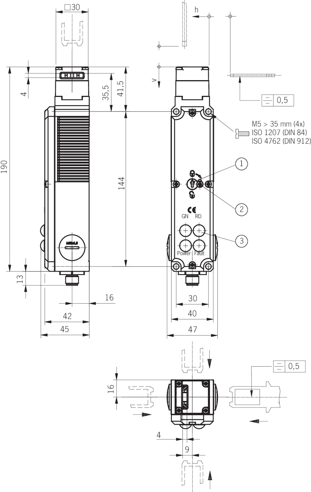


Stp3a 4141a024sem4as1 Safety Switch Stp Asi Plug Connector M12 Closed Circuit Current Principle Euchner More Than Safety


Volvo S40 Wiring Diagram Pdf Download Manualslib
12 Wiring There are 2 wiring methods for the RTD module and PT100 temperature sensors — twowire and threewire connections When wiring with two wires, first jumper across A1 and B1and and B2 respectively, then connect PT100 sensors and to the RTD module according to the following diagram on the left (Note A1B1, B2 and C1C2Jul 21, · Square D 100 Amp Panel Wiring Diagram Collections Of Square D 100 Amp Panel Wiring Diagram Download 11 Fantastic Graphs Aluminum Wire 100 Amp Subpanel – Wiring Diagram Square D Individual Subpanels Hom612l100fcp 64 1000 Subpanel Wiring Shop Square D Homeline 80 Circuit 40 Space 0 Amp Main Breaker PlugNew wiring diagram designations Current designation KMS – SA1 NORM actuator MSP – actuator with AM controls ACP – actuator with AC1 controls SD – actuator dimensional diagram New designation TPA – S NORM actuator MSP – actuator with AM controls TPC – actuator with AC2 controls ACP – actuator with AC1 controls


Wiring Diagram Scannerdanner Wiring Diagram Autodata 1 3 Wiring Diagram Peugeot 7 Dv4td 8hz 1 4


Abf Engine Wiring Diagram
Sep 13, · Variety of pt100 sensor wiring diagram A wiring diagram is a streamlined conventional pictorial representation of an electric circuit It shows the parts of the circuit as streamlined forms, and the power and signal links in between the devicesApr 08, 14 · I have looked for diagrams on several of the newer generation of tractors and all I have been able to find are images of the wiring harness that really gives no insight into what controls what I am thinking you are going to have to find someone who has a chassis service manual once you have determined the model number of your tractorSep 01, 16 · The 34 VZFE motor is a very common and popular swap into earlier Toyota pickup trucks to replace the 30 3VZE If you are unable to provide the wiring diagrams, please just say so For you to give inaccurate information is very unprofessional The challenge lies in connecting the dash and ignition wiring to properly power the 34 ECU


Tp Link Wireless Switch Wiring Diagram Page 1 Line 17qq Com


Abf Engine Wiring Diagram
TP 1000/2 AFABAQELX1 Singlestage, closecoupled, volute pump with inline suction and discharge ports of identical diameter The pump is of the toppullout design, ie the power head (motor, pump head and impeller) can be removed for maintenance or service while the pump housing remains in the pipeworkConnect the GREEN WITH BLACK STRIPE wire to the unlock wire Page 14 Antenna Placement ANTENNA PLACEMENT ANTENNA For best results, run the antenna (YELLOW WIRE WITH BLACK TIP from the back of the unit) as high up in the dash and as straight as possible Do not place the antenna next to any metal parts or the vehicle's main computer controlDec 09, 17 · Hx 0453 Of Wiring 3 Wire Rtd Pt100 Thermocouple Diagram Free Pt100 rtd colour codes iec temperature transmitter e k s b txblock usb sensor connections wire general purpose 2 3 and 4 rtds what is the how sensors work thermocouples wiring diagram 1999 f250 21 multi point probes tachometer in or connection ma auber instruments two transmitters they
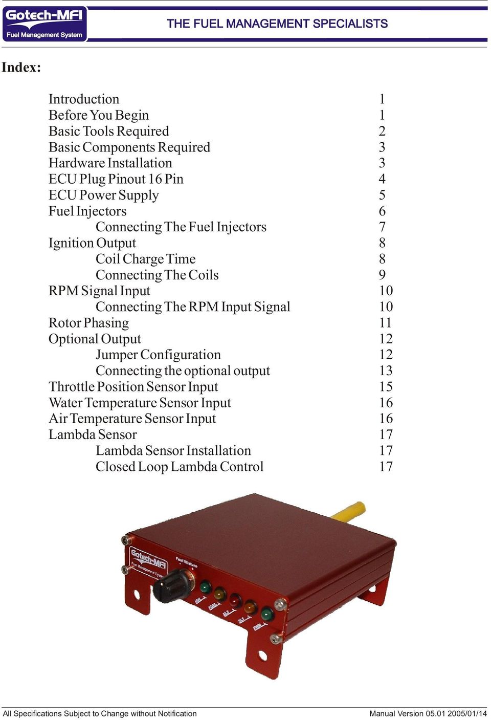


Mfi Instructional Manual Version Pdf Free Download


02 Grand Am Engine Diagram Wiring Diagram Overview Device Halt Device Halt Aigaravenna It
TP100 3D contact probe with software interface included The DeskCNC machine controller includes probing software The controller scans a 3D surface with the TP100 probe, filters, smoothes, and then compensates for the probe tip diameter, before creating a 3D surface model saved in an STL file format The surface can be remachined using the DeskCNC CAM, or theView and Download Suzuki T250 service manual online T250 motorcycle pdf manual download Also for T350Alex Okun 3 1 1103 pm Size in deskcnc Support 14 1 1052 am Interfacing with qaud encoder?
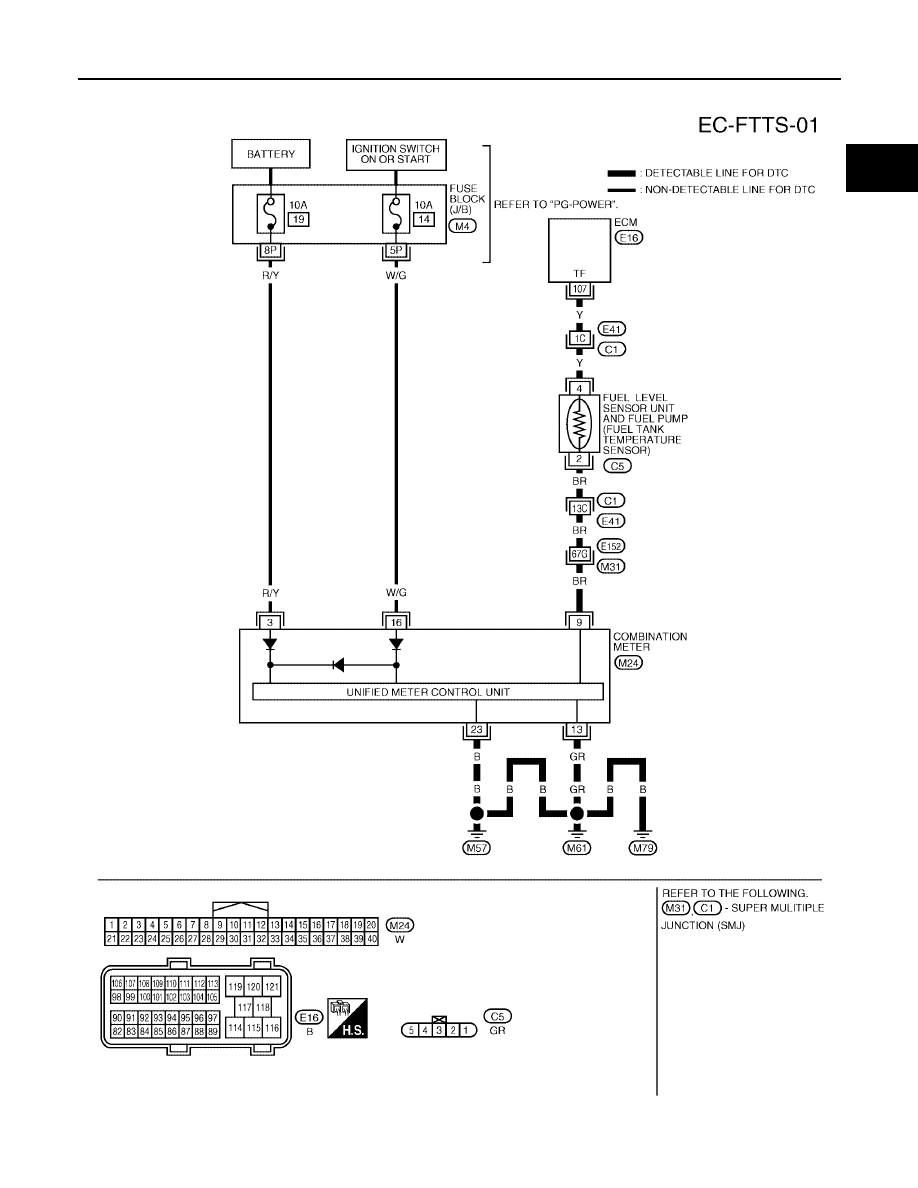


Nissan Pathfinder 06 Year Manual Part 184
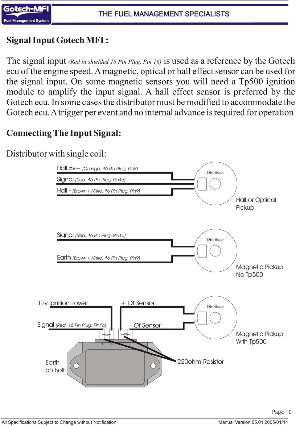


Mfi Instructional Manual Version Pdf Free Download
A wiring diagram is a straightforward visual representation of the physical connections and physical layout of your electrical system or circuit It shows how a electrical wires are interconnected which enable it to also show where fixtures and components may be coupled to the system When and How to Use a Wiring DiagramTP100 Digital temperature relay TR100 is designed for measuring and controlling a device temperature via four sensors connected according to a two or fourwire diagram, with subsequently displaying the temperature on screen and generating alarms when any parameters fall beyond set limitsTp100 Wiring Diagram Gallery how to install an msd 6a digital ignition module on your 1979 1995 of tp100 module wiring diagram, image source rimcaseinfo astonishing 03 ford focus radio wiring diagram 38 with additional 00 chevy s10 to 01, image source blogitiacom
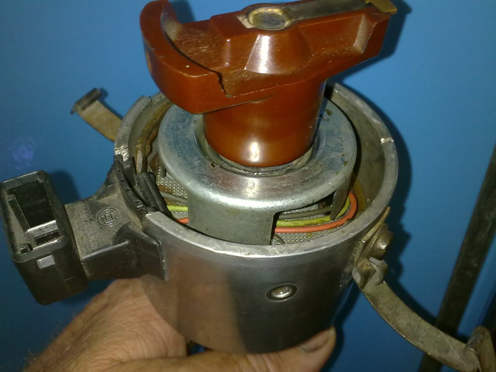


Convert To Electronic Ign Page 2 Aircooled Vw South Africa


Cb160 Wiring Diagram Wiring Diagram Blog Layout Angel Layout Angel Arredhome It
A further possibility to substantially decrease the influence of the cabling is to increase the conductor crosssection With a crosssection of 05 mm 2 the line resistance is only 0036 Ω/m or 01 °C/m Both options (3/4wire connection or increasing the crosssection) lead to a higher cost in the cabling, which can be problematic, especially in costsensitive markets such as machineBasicpindioderfswitch Controlcircuit Circuit Diagram Seekic Wiring Diagram Database Tp 100 Module Wiring Diagram のギャラリー Dicktator Tp100 Ignition Module Incl Plug PinsRatioMetric 2Wire RTD application Advantage •Very simple RTD connection •IDAC generates the sensor excitation and the reference voltage •Noise and drift of the Ref voltage are correlated and therefore canceled •Only one current source no mismatch •Up to 7 RTDs are possible Disadvantage Voltage drop across the line resistance


Diagram Database Free Read Or Download Diagram Database


Commax Interphone Tp 90rn Intercom System Connectable Up To 90 Units Ebay
Oct 17, 17 · I need help with the wiring for the TP100 with the harness, I dnt want to burn the module or anything else Three wires , one red, one blue and one green and white that has an eye terminal on it Correct me if I am wrong here Red will go to the positive of the coil, blue will go the negative and the green&white wire ????


Tp100 Module Golf


Tp N 701 Installation Manual Manualzz


Sea Ray Electrical Wiring Diagram Page 1 Line 17qq Com
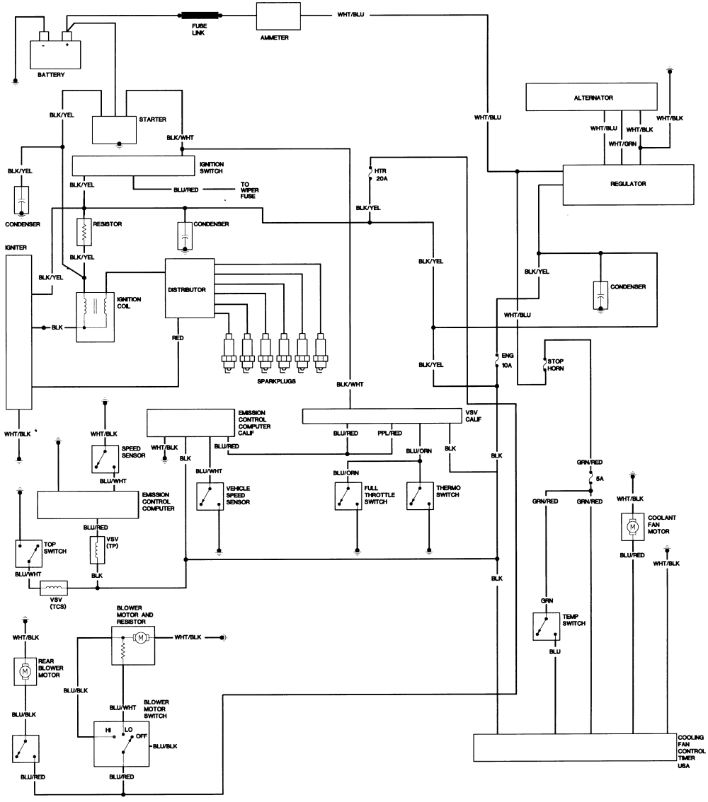


Fj40 Wiring Diagrams Ih8mud Forum


Diagram Database Free Read Or Download Diagram Database


Tp Link Dimmer Switch Wiring Diagram Page 1 Line 17qq Com


Rev Counter Help Electrical Connection The Volkswagen Club Of South Africa


Kteb 2 1 Tp Emi Keystone Ballast


90cc Atv Wiring Diagram With For Chinese 110 Motorcycle Wiring 90cc Atv Electrical Diagram


92 Ford Ranger 2 3 Engine Wiring Universal Wiring Diagrams Device Verify Device Verify Sceglicongusto It



Daewoo Tp 605guc Service Manual Pdf Download Manualslib


Volvo S80 06 15 Electrical Wiring Diagrams Youtube


Bmw R1150r Electrical Wiring Diagram 6 Electrical Wiring Diagram Electrical Diagram Electrical Wiring


3 1 V6 Engine Diagram Fusebox And Wiring Diagram Wires Pit Wires Pit Sirtarghe It
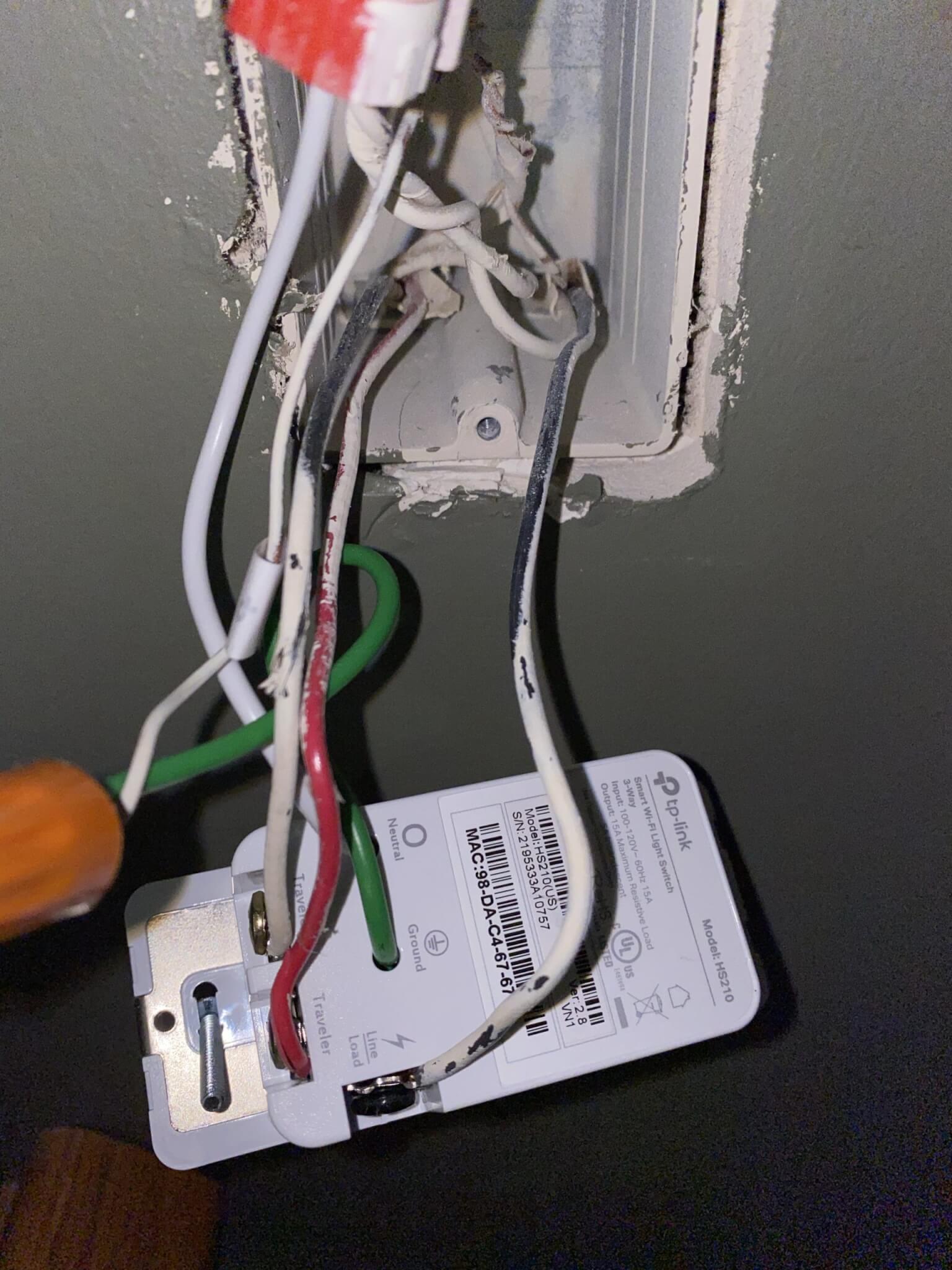


Replacing A 3 Way Switch With A Tp Link Hs 210 3 Way Smart Switch Automated Home Party


Gmc Truck Engine Diagram Universal Wiring Diagrams Wires Realize Wires Realize Sceglicongusto It


Auma India Weather Proof Actuator Catalogue Part 3 Sample Tp And Wdp Sheets Ilovepdf Compressed Components Electric Power


Nissan Murano Z50 04 Year Manual Part 104


Commax Video Intercom Wiring Connection Hd 1080 Urdu Hindi Oppo F9 Camera And Mic Test Youtube


Suzuki Swift Wiring Diagram Diagrams Throughout Electrical Diagram Electrical Wiring Diagram Repair Guide


Tp100 Wiring Diagram Ford Focus Stereo Wiring Diagram Rccar Wiring Nescafe Jeanjaures37 Fr


Pin On Wiring


Dicktator Connection Diagrams September 09 Ignition System Fuel Injection


Tp100 Wiring Diagram Remote Wire To Fuse Box Bonek Tukune Jeanjaures37 Fr
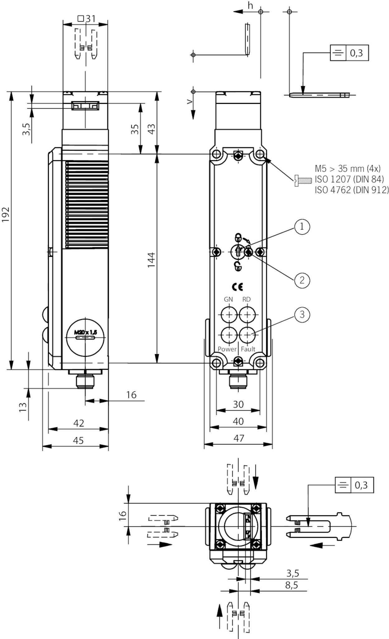


Tp3 4141a024sem4as1 Safety Switch Tp As1 Plug Connector M12 Closed Circuit Current Principle Euchner More Than Safety


Mfi Instructional Manual Version Pdf Free Download


Tp Link Smart Switch Wiring Diagram Page 1 Line 17qq Com


Hilti Tp 400 Service Manual


Volvo V70 Xc70 S80 08 Electrical Wiring Diagram Manual Instant Download By Heydownloads Issuu


Dan S Motorcycle Various Wiring Systems And Diagrams


Tpa Auma Actuators Inc


Tp6744 Electrical Components Electric Power


Volvo Alternator Wiring Diagram Free Download Area Paveme All Wiring Diagram Area Paveme Apafss Eu


Mfi Instructional Manual Version Pdf Free Download
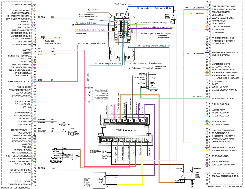


Pontiac Wiring Harness Fusebox And Wiring Diagram Circuit Pit Circuit Pit Sirtarghe It


Abf Engine Wiring Diagram


Mfi Instructional Manual Version Pdf Free Download


Hs2 Wiring Question Mystery Help Needed Tplinkkasa


I Am Installing A Tp Link Hs0 And What Looks To Be An End Of Circuit Situation I Need Some Advice On How To Make This


Ppt Northeast Generation 2 Training Powerpoint Presentation Free Download Id


Nissan Pathfinder 06 Year Manual Part 184


Diagram 3 Way Switch Wiring Diagram Power At Switch Full Version Hd Quality At Switch Diagramgantt Artcache It


I Believe The Thing I Need Is A Wiring Diagram For A 1998 Olds 3800 Series It Has A No Spark Condition It Does Have
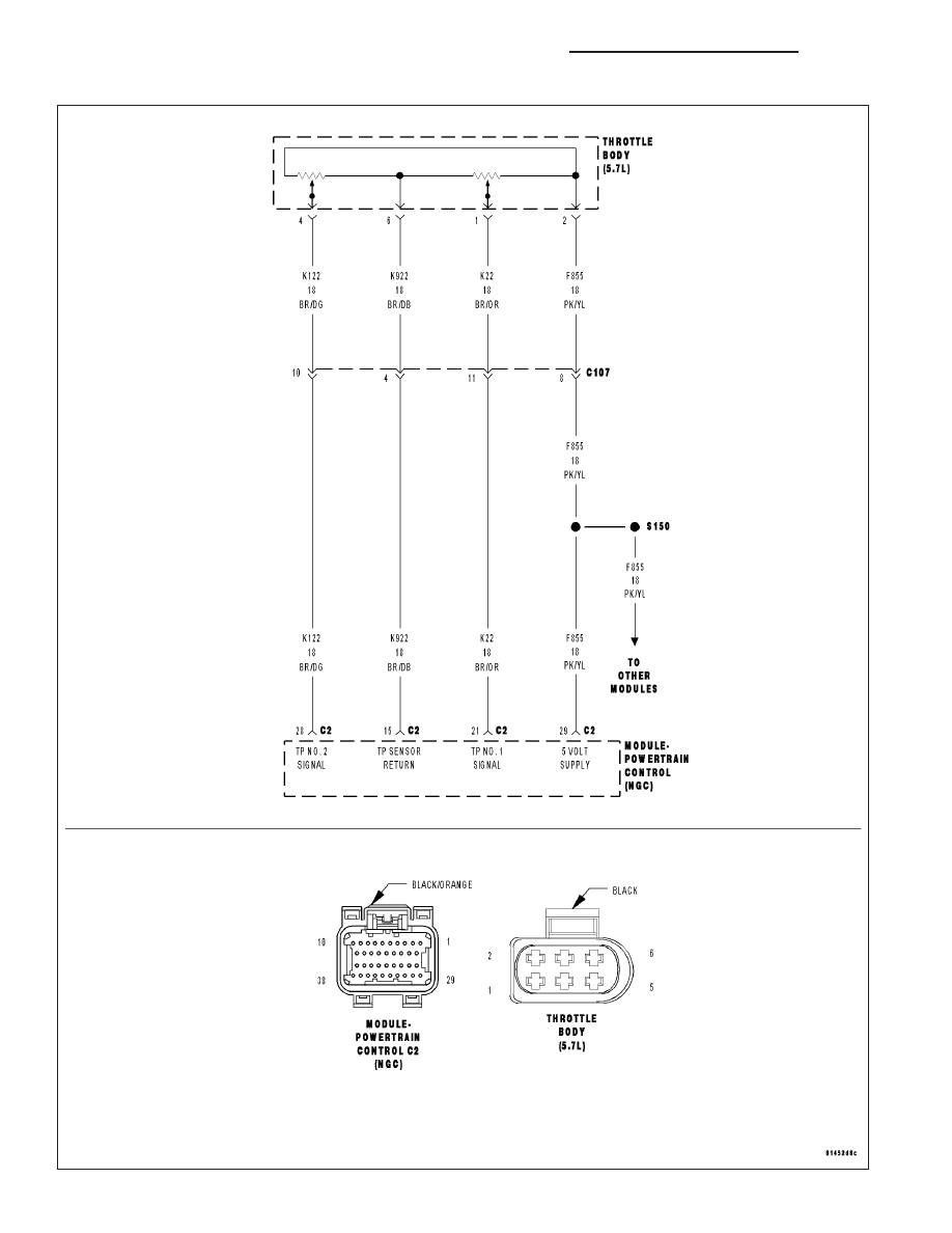


Dodge Ram Truck 1500 2500 3500 Manual Part 803


Nord Gsm Metal
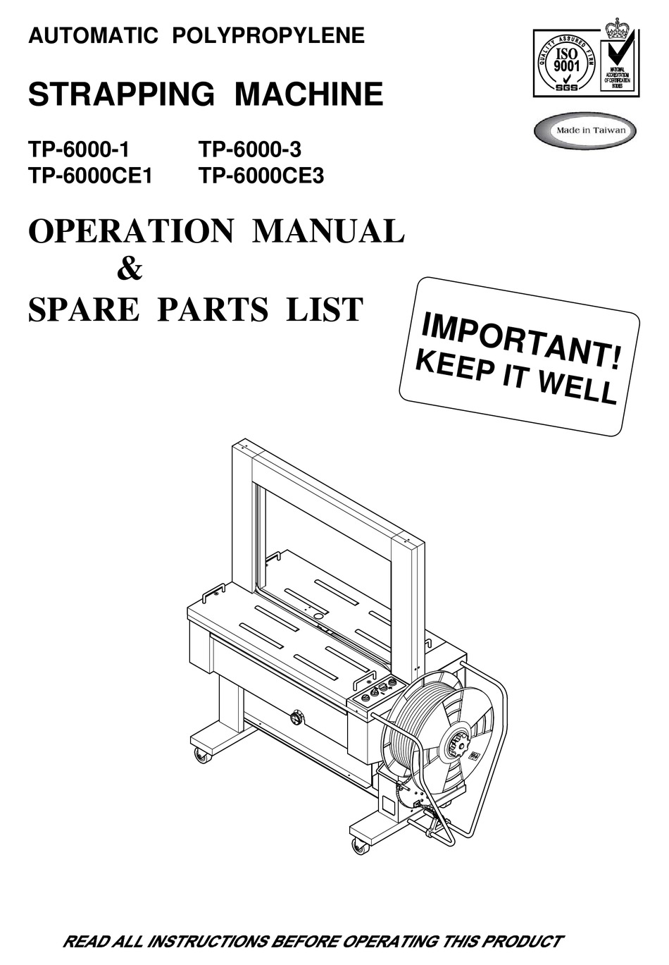


Transpak Tp 6000 1 Operation Manual Spare Parts List Pdf Download Manualslib


5 3l Wiring Diagram Universal Wiring Diagrams Wires Realize Wires Realize Sceglicongusto It


Volvo C30 Wiring Diagram Pdf Download Manualslib


Volvo 940 1994 Wiring Diagram Pdf Document
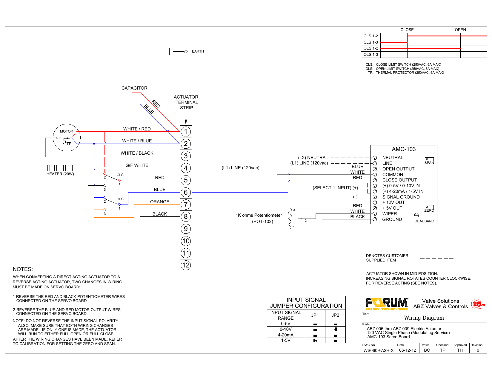


Wiring Diagram Notes Amc 103 Jumper Configuration Manualzz


1997 Ford Engine Wiring Diagram Diagram Design Sources Wires Peace Wires Peace Nius Icbosa It


0 件のコメント:
コメントを投稿